What is a Traveling Cylinder?
Traveling Cylinder Plot (TCP) is one of a collection of tools that operators have traditionally used to plan and drill safely through a maze of wells. Most common usage is on wells that are drilled from offshore platforms or wells that are drilled from land pads with multiple adjacent wells. Their principle usage is in the vertical hole sections near the surface where collision risks are generally the highest. The development of the TCP is a clever 2D solution to a 3D problem that was formally introduced to the drilling industry in 1991 by John Thorogood and Steve Sawaryn (SPE 19989). The TCP effectively leveraged the computer technology of the day, and also brought forth a manageable paper plotting system that is especially effective for vertical well space. These plots are still widely used in the directional drilling industry, although their use is likely to diminish as effective 3D computer programs such as Hawkeye replace their usage with superior visualization tools.
A word on Ladder Plots (LDP)
Before defining the traveling cylinder plot, first think about what a ladder plot is; it plots the uncertainty and the survey of each adjacent well as a function of distance vs MD of the reference well. This is an invaluable plot because visually one can immediately see any potential problem areas as illustrated in the plot below. An optimized ladder plot will be calculated with the 3D minimum distance algorithm and all crossings of all wells will also be calculated. This is important for a number of reasons, but the principle reason is that the nearest points are nearly always at crossings. Not all crossings are collisions. A single well may have many crossings with another well and none of them would collide, but all of them would share the mathematical property that at those points the line that connects the two wells is perpendicular to both wells, not just one well. In addition to this, not all closest approaches are actually crossings. A well can approach the reference well and then turn away, without crossing. This idea of crossings and close approaches turns out to be critical to proper display of a Traveling Cylinder Plot, so don't forget it.
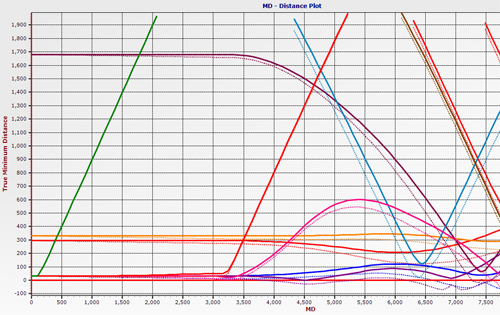
Since many wells can be viewed at once on a ladder plot it is a far more efficient and user friendly report than a long textual report that would contain the same information. There is one problem: there is no directional information inferred by the LDP. A directional driller can see that there is a potential collision risk at such and such a depth, but he has no way of looking at the LDP and defining what direction the risk is located.
Enter the Traveling Cylinder Plot. The directional driller or well planner can look at this plot and easily identify the direction of the collision risk and come up with a directional steering plan to mitigate the risk.
How to read a Traveling Cylinder Plot
Understanding how to read a traveling cylinder plot can be a bit of a challenge. The first issue to comprehend is that the plot represents a two dimensional representation of a solidly three dimensional problem. The center of the plot represents all the points along the reference well, regardless of the geometry of the well. For a well planner the reference well would be the plan and for a directional driller the reference well would be his as-drilled plus his projection to the bit and beyond the bit, if the plot is being maintained by a computer. If a wall plot is being used by the directional driller (DD), the wall plot will have the proposal as the reference curve, and the DD plots his as-drilled points on the wall plot. Should his plot points cross a no-go zone on the TCP then that would be indicative of an operator’s rule-set violation. A DD needs to know how to calculate the plot points on a calculator or by hand, should the computer program he is using not provide the plot points for him.
Since the TCP is normally used in vertical portion of wells the natural plane on which to measure distances is the normal plane, the plane which is perpendicular to the direction of the reference point at any given depth. In vertical wells this plane approximates the TVD plane. For low inclinations, which is what the TCP is used for primarily, the DD can use the EW,NS coordinates of the survey to calculate his plot point. Although this is not entirely accurate the discrepancies are minor. With non-vertical wells the normal plane is the plane the directional driller uses to steer from high side. In vertical wells the directional driller steers with magnetic tool face so the TCP is normally referenced to either true north or grid north. Some companies demand that true north always be used, but there are some very good reasons to use grid north if a grid system was used to plan the wells. Certainly, if one were to use a traveling cylinder plot in higher angle holes the use of GTF reference instead of north reference is desirable since the goal of a TCP is to provide and effective steering guide.
Constructing the Traveling Cylinder Plot
Since the reference well is represented by a single central point on the TCP, plotting all of the uncertainty ellipses for all of the depths around that point would result in a blur of meaninglessness at the center of the plot, since it is near impossible to associate which ellipse is associated with a given depth. The comparison wells, on the other hand, can have meaningful ellipses drawn around their survey points, but they only represent half the uncertainty. In order to overcome this issue, a TCP summarizes the uncertainty of the reference well with the uncertainty of the offset well and displays that uncertainty around the offset well. This is accomplished by summarizing the covariance matrices (The covariance matrices are the mathematical tool that is used to determine the uncertainty of multidimensional uncertainty). of the reference well and the offset well, and then displaying the resulting ellipse/ellipsoid/elliptical cylinder on the offset well. With this method the reference well in the center stays unmarked and thus uncluttered.
Shortcomings of the Traveling Cylinder Plot
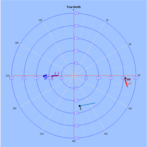
Shortcoming 1:One rather critical issue with TCPs in vertical wells is how to handle “flipped” survey stations. If all the crossings of a well are not inserted into a survey list, and the only the surveys are used to calculate least distance then there are instances, as the one shown below indicates (fig2), where it appears on the TCP that there is a head on collision with the reference well. One can easily see from the plot that these two wells did not collide, so what is the problem? The problem is that no crossing was calculated between the two successive surveys, as it should have been. What the crossing represents is the point of closest approach between the offset segment bound by the two surveys and the reference well. If the crossing is determined and then plotted it clearly shows how the offset well misses the reference well. There have been other ways of dealing with this issue, but this is the best way.
Shortcoming 2:Another issue with TCPs is that in tight spiraling adjacent wells, plotting the entire depth of the reference well can lead to some confusing imagery, so it is best to plot the TCP out in sections so that several TCP plots are used for the entire well.
Shortcoming 3:The TCP requires the user to abstract numerous concepts and for a casual user, such as a company representative, it can be difficult to understand at first glance.
Shortcoming 4: TCPs also suffer from the limitations of normal plane distance calculation, a method that will only pick a point on a well that intersects with the normal plane of the reference well, and completely miss a well that is directly in front of the bit. (Of course, a good complete anti-collision policy should pick up that type of collision easily).
Shortcoming 5: Another weakness is that for highside calculations on the normal plane, manually calculating the point of intersection and determining the appropriate plot point without a computer or a rather complex calculator program is highly impractical. Computer programs such as Hawkeye™ which maintain a dynamic TCP while drilling are the best way to use a TCP, as they help to reduce the amount of human error that can occur by mis-plotting TCP data manually. A computer program can also use the as-drilled instead of the proposal as the reference well since the errors attributed to the reference well are actual as opposed to “planned.”
In Conclusion
The judicious use of a TCP in conjunction with ladder plots and proximity reports makes for an effective anti-collision package. The advantage to the method is that it can be maintained on a wall plot and does not necessarily have to be maintained by a directional computer program. Once a DD understands how to use the plot he has a very effective steering tool to aid him in avoiding other wells. However, it is likely that the use of TCPs will diminish as robust 3D interfaces become more widely available. This is because the visualization of such systems is immediately comprehensible and much less likely to foster misunderstandings.
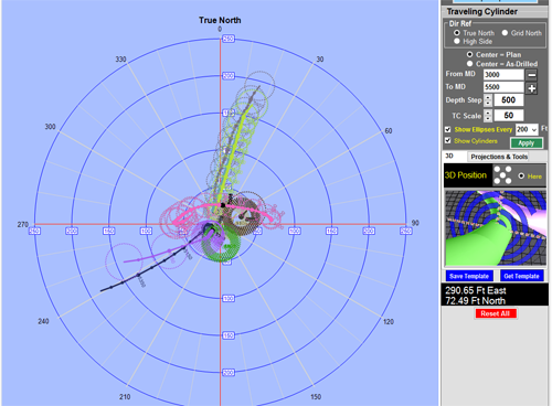
HawkEye’s Traveling Cylinder Plot
One may reasonably ask why Hawkeye has need of a traveling cylinder plot when it has such great 3D visualization tools? The initial answer is that some of Hawkeye’s users wanted to have a TCP because of their familiarity with them, and also because their customers demanded it. The challenge then, was finding a way to bring the TCP to the next level; beyond what anyone else has done with them. The final answer to the aforementioned question is that the Hawkeye TCP provides an exceptionally good interactive interface that can help users to quickly grasp the proximity issue at hand by tying together the 2D plot with 3D visualization.